
By Rama Pal, S. Islam, M. Muruganandam, Vibha Singhal, Trisha Roy and Uday Mandal ICAR-Indian Institute of Soil and Water Conservation
Introduction
Today we face challenges of water scarcity, wastewater discharge, landscape limitation and ecological conservation. As per the CPCB report 2021, the total wastewater generation in India is 72,368 MLD out of which 72% is discharged untreated into surface water bodies. The sustainable solution to this problem could be innovative water management strategies that integrate technology with landscape design and enhances ecosystem services. Constructed wetlands
(CWs) are such treatment systems that use microbial assemblages, wetland vegetation, and soil resources to improve water quality through natural processes. The CWs provide cost-effective wastewater treatment solutions encouraging the reuse of treated wastewater which not only prevent pollution of freshwater resources but also reduces consumption pressure leading to improvement in the delivery of freshwater ecosystemservices. The two primary types of CWs are i) surface flow (SF) and ii) subsurface flow (SSF). Most of the time, the heavily vegetated surface flow or free water surface (CWs) has a standing water column that is immediately exposed to the atmosphere and sunlight and is less than 0.4 metres tall. Horizontal flow (HF) and vertical flow (VF) systems are two subsurface flow CW classifications based on the direction of water flow through the porous material. To prevent clogging of the porous filter material, SSF CWs are only utilised after primary treatment of waste water with low particle levels (i.e., grey or black). In SSF CWs compared to SF systems, the contact area between water and bacteria/substrate is significantly greater, which reduces the amount of space needed (Vymazal et al., 1998).
In HF CWs, water enters the inlet and slowly moves horizontally through porous medium until it reaches the outlet zone, where it is collected and released (Fig. 1). It is used to treat wastewater in the secondary or tertiary stages (e.g. greywater or blackwater). The majority of organic materials are broken down by facultative and anaerobic microorganisms; vegetation, on the other hand, provides a limited quantity of oxygen to the root zone to enable the development of aerobic bacteria. As a result, both aerobic and anaerobic processes of decomposing organic waste take place in HF CWs, leading to efficient removal. The absence of oxygen prevents complete nitrification (Langergraber& Haberl, 2004) in HF CWs. VF CWs with intermittent loading have the capacity to remove ammonia nitrogen effectively, hence are extensively used nowadays (Fig. 2). VF CWs are used as secondary or tertiary treatment technology (for greywater or blackwater). A mechanical dosing system is used to dose pre-treated wastewater onto the surface from above, such as from a septic tank or an Imhoff tank. The water is collected in a drainage pipe at the bottom of the basin after vertically descending through the filter matrix. Treated water can be used for irrigation, aquaculture, and groundwater recharge, or it can be discharged into surface water.
Removal Mechanisms and efficiencies of Constructed Wetland
The main mechanism of treatment through CWs comprises physical (adsorption, sedimentation, filtration), biological (microbial or plant enzymes mediated degradation of pollutants, accumulation of pollutants by plants/microbes), and
chemical transformation (redox, precipitation, volatilization, photolysis) with solid and liquid separations. Contaminants removal in root zone involves rhizodegradation process by microbial activity. The heavy metals are reduced through
phytostablization and phytoaccumulation. Organic material (BOD) is removed by biological degradation, sedimentation, and microbial uptake. Suspended solids are removed by sedimentation and filtration. Nitrogen is removed by plant/microbial uptake, sedimentation and nitrification/denitrification. Phosphorus undergoes sedimentation, filtration, adsorption and plant/microbial uptake. Pathogens are removed by natural die-off, adsorption, filtration, sedimentation, and UV degradation.
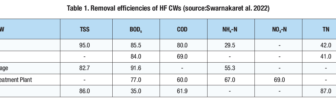
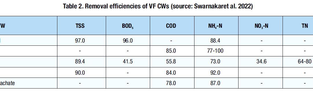
Tables (1 and 2) depict removal efficiencies of both the constructed wetlands. The removal efficiency of VF CWs for ammoniacal nitrogen removal is high as compared to HF CWs which is due to the fact that a high aerobic environment exists in the filter bed of VF CWs which facilitates the nitrification process. However, nitrification and reduced denitrification due to high oxygen availability results inincreased nitrate concentration in the effluent, as a result,VF CWs have lesser nitrate removal efficiency.Whereas in HF CWs anammox reaction (anaerobic process) directly converts ammoniacal nitrogen into dinitrogen resulting inhigher nitrate removal efficiency.
Role of plants in Cws
The selection of CWs plants depends on the type of CW system, survival in the local climate, pollutant strength of wastewater, and substrate. Any native plant with a deep and wide root system that can grow in wet and is tolerant to harsh chemicals in wastewater to be treated. Most commonly, emergent herbaceous plants are used in CWs example Phragmites australis, Typha latifolia, Canna indica, Arundo donax, cattail, vetiver grass, and water grass. The plantation density (numbers per sqm area) depends on the available surface area of the filter bed.
Plants in CWs provide a habitat for wildlife and aesthetic value to the environment. In colder locations/seasons, dead plant debris acts as a natural insulation layer to protect and maintain biological activity in the filter bed. Additionally, plants transfer oxygen into the filter bed via their roots and create an aerobic environment for microbial growth in the root zone. However, the most important role of vegetation’s root system is to maintain the filter’s permeability (Hoffmann et al. 2010 and Tilley et al. 2008).
Design Considerations
The treatment target, as well as the hydraulic and organic loads of the influent, determine the design of horizontal and vertical subsurface flow-constructed wetlands. The cross-sectional area (width multiplied by depth) controls the
maximum allowable flow, while the surface area (length multiplied by width) determines the removal effectiveness of both wetlands. The design criteria also involve decisions on compartmentation and the number of parallel flow pathways in HF CWs. A surface area of about 5 to 10 m2 and 1 to 3 m2 per person equivalent is required for HF and VF CWs, respectively.
A horizontal subsurface flow constructed wetland is a sizable channel filled with gravel and sand and covered with aquatic plants. To ensure subsurface flow, the water level in HF CWs is kept at 5 to 15 cm below the surface (Tilley et al 2008). An inlet cascade can aerate the influent to aid oxygen-dependent processes like BOD reduction and nitrification. The vertical flow constructed wetland may be planned as an above-ground structure or as a shallow excavation. Pre- and primary treatments are crucial to get rid of solid contaminants (such as faeces or kitchen waste) as well as grease or oil from the liquid because clogging is a major issue in both wetlands.
Operation
In an HF CW, pre-treated wastewater moves slowly in a horizontal course through the porous medium beneath the surface of the filter bed until it reaches the outlet zone. To stop leaching, the filter bed should be lined with an impermeable liner (clay or geo textile). The filter bed is wide and shallow to increase the contact time between the flow path of the water with plant roots. The inlet zone is well-designed and wide to avoid short-circuits and evenly distribute the flow of water. In order to improve treatment efficiency, the water surface is changed through the outlet height which is variable. An adjustable standpipe is used to manage the water level at the outlet. As per the design recommendation, a water level of about 60 cm in the outlet is kept at roughly 5 to 15 cm below the surface of the CW to prevent anaerobic conditions in the bed. The oxygen supply plays a crucial part in the effectiveness of the treatment. In comparison to a vertical flow wetland, horizontal filter beds have a much smaller entrance and very little external oxygen transfer, hence, they need a larger area.
In a VF CW, wastewater is intermittently fed to the surface filter beds (either by pump or self-acting syphon device), where it then flows vertically down the filter layers and into a drainage system at the bottom. In some instances, distribution pipes are covered with gravel on top to prevent standing water. Intermittent short-term loading intervals (4 to 12 doses per day) and lengthy resting intervals, during which the wastewater percolates through the unsaturated substrate and the surface dries up, define the treatment process. The oxygen transport is improved by intermittent batch loading, which also results in significant aerobic degradation activities.
Substrate
In an HF CW, the bed is typically filled to a depth of 0.5 to 1 m using small, round, equally sized gravels (3 to 32 mm in diameter). The gravel ought to be clear and devoid of fines in order to prevent clogging. Although more prone to clogging than gravel, sand is also acceptable (Eawag/Sandec 2008). Large-sizedgravel should be used to build the inlet and outlet zones.
In a VF CW, the filter bed consists of layers of gravel and sand at the top, then a layer of drainage gravel at the bottom (minimum 20 cm). The permeability of the substrate should be in accordance with the hydraulic and organic loading. The drainage pipes at the bottom are covered with gravel. On top of this gravel layer, there is an actual filter bed which consists of a sand layer (40-80 cm thick). On top of the sand layer, there is another gravel layer (about 10 cm) for preventing water from ponding on the surface. The top gravel layer does not contribute to the treatment process.
The substrate which is recommended to be used in the subsurface flow of CW’s filter beds are:
• The hydraulic conductivity (kf-value) of sand should range between 10-3 m/s.
• The thickness of the filtration sand layer should range between 40 to 80 cm.
The substrate should not contain very fine materials like loam, silt or clay. The selection of filter bed material also depends on the local conditions and the experiences of the design engineer.
Health Aspects/Acceptance
Pathogens are significantly removed through filtration, natural decay, and predation by higher organisms. Depending on the intended reuse application, disinfection (via tertiary treatment) may be required for domestic wastewater (Hoffmann et al. 2010). Any pathogenic organisms that may come into touch with people or wildlife are kept to a minimum because of the water’s subsurface movement. Settling wastewater in the pre-treatment facility is a major health hazard. A proper emptying procedure (either powered by humans or propelled by motors) can reduce health concerns (Tilley et al. 2008). Sludge must then be properly processed, perhaps in drying beds or composting facilities. The risk of mosquito breeding is decreased because there is no standing water.
Costs Considerations
The cost of sand and the price of land have a significant impact on the capital expenses of created wetlands. However, net present value or whole-of-life costs, which also include yearly operating and maintenance expenses decide the total
expenditure of the treatment of wetlands. Constructed wetlands are natural systems that function extensively in comparison to other intensive (high-rate) aerobic treatment alternatives (such as activated sludge). The treatment may take more time and land, costs can be kept to a minimum owing to operations that use little to no electricity and can employ trained locals as operators (low-skilled people). Additionally, there is no requirement for expensive machinery, spare parts, or chemicals (Gauss 2008). Constructed wetlands are typically less expensive to build than high-rate aerobic plants, although they are typically more expensive in terms of capital expenditures for larger plants. For large-scale treatment wetlands, plants and liners may substantially add to the costs if they are unavailable locally. Moreover, design and construction of subsurface-flow constructed wetland requires skilled technical staff.
Scope of Constructed Wetlands in Indian Agriculture
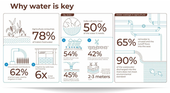
Since India’s total gross irrigated area is 62 Mha) (ICID, 2018) which would require approximately 910 trillion liters of water for irrigation in 2025 (Fig. 3), therefore, with a total volume of available wastewater (72,368 MLD or 26.4 trillion liters per year) generated in India, 1.8 Mha land can be potentially irrigated (Table 3) which accounts 2.9% of total irrigated area in the country. The use of wastewater for irrigation will save 3% of the freshwater used in agriculture.
Conclusion
CWs can be utilized to treat wastewater from industries or other types of development. The goal of reducing carbon emissions by implementing these biological CW treatment systems can be met along with significant financial savings
and earning carbon credits to support a Clean Development Mechanism. Under the current scenario of wastewater discharge in India and the reduction in freshwater availability due to increasing consumption by various sectors as well as water quality deterioration of freshwater bodies, wastewater use for irrigation is highly recommended after proper treatment with cost-effective green technologies like CWs in order to sustain Indian agriculture.